Table of Contents
Key PM Components in a Shock Absorber
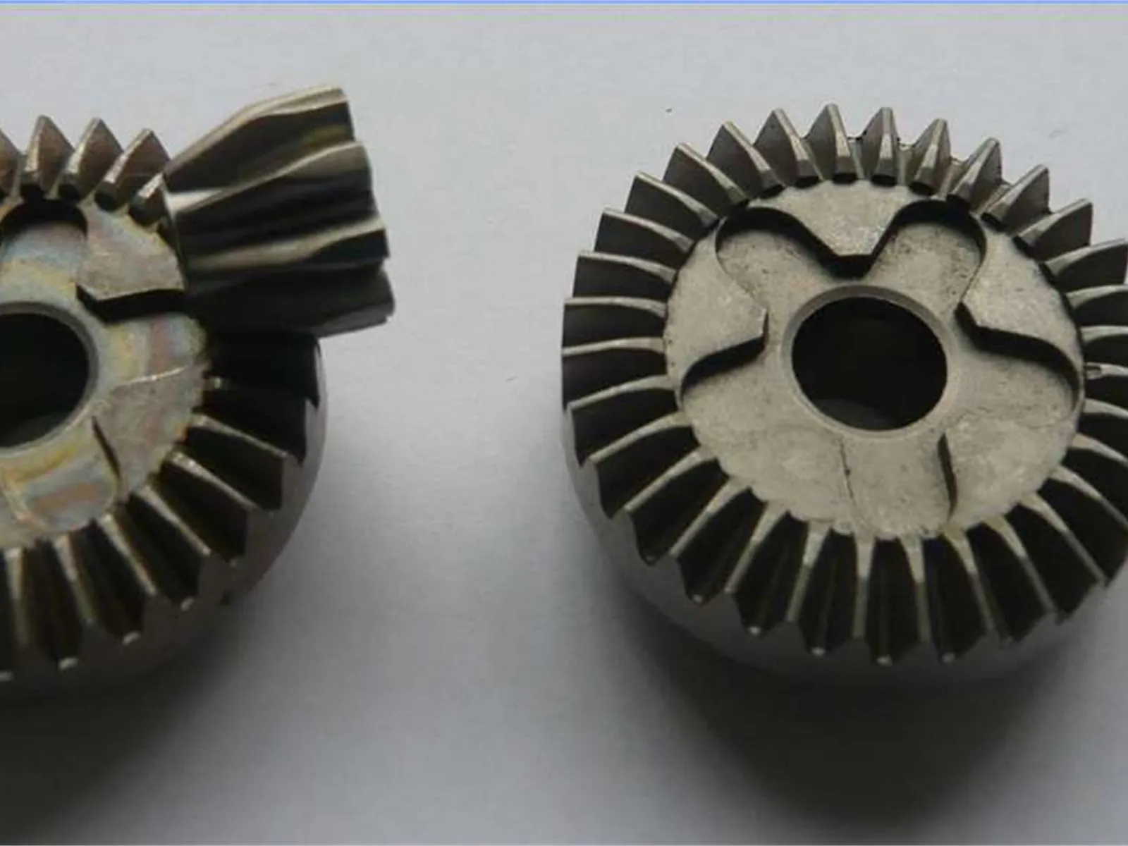
A typical monotube or twin-tube hydraulic damper uses several PM components:
Piston Valve Body
The piston travels back and forth inside the main tube as the damper compresses and extends. The piston body houses the valve disc stack that meters oil flow and determines damping force. In many designs, the piston body is a PM part:
- Complex axial geometry: annular oil passages, valve seat lands, snap ring grooves, and a central bore for the piston rod attachment
- Tight bore tolerance for the rod connection and valve fit
- Tight OD tolerance for consistent clearance with the tube wall
- Oil passages formed in the pressing to minimize secondary machining
PM piston bodies are widely used in passenger car and motorcycle damper programs. The combination of complex axial geometry, tight tolerances, and high volume (one per damper per corner) makes them a strong PM fit.
Base Valve Body (Twin-Tube Designs)
The base valve sits at the bottom of the inner tube in twin-tube shock absorbers. It controls oil flow between the inner and outer tubes and sets the compression damping baseline. Similar to the piston in geometry and PM suitability: complex axial profile, oil passage ports, valve seat surfaces, and tight OD fit to the tube.
Rod Guide / Piston Rod Bushing
The rod guide seals and supports the piston rod where it exits the top of the damper. Sintered PM bushings are used in the rod guide assembly:
- Bronze PM or iron-copper PM bushings provide wear resistance against the rod surface
- Oil-impregnated PM bushings provide initial lubrication before road film establishes
- Tight bore tolerance ensures consistent rod clearance for good sealing
End Caps and Mounting Hardware
End caps, compression stops, and mounting bracket inserts that are axially formed and do not require complex lateral geometry are PM candidates at high automotive volume.
Materials
Piston and valve bodies:
Iron-based PM alloys are standard for structural piston and valve bodies. Common choices:
| Grade | Typical use | Notes |
|---|---|---|
| FC-0208 | Standard piston body | Good strength, dimensional stability |
| FN-0405-HT | Higher-load applications | Better fatigue, higher strength |
| FC-0208-90 | Moderate strength, as-sintered | Cost-effective |
For pressure-tight valve applications, resin impregnation is standard to seal interconnected porosity and prevent oil weeping through the PM wall.
Rod guide bushings:
- Bronze PM (CT-1000 or similar): self-lubricating, good rod surface compatibility
- Iron-copper PM (FC-0205): cost-effective, oil-impregnated
- Bimetal bushings (PM backing + PTFE or polymer liner): used in some precision damper designs for very low friction
Pressure Tightness
Shock absorber dampers operate at internal oil pressures that vary by design but can reach 80 - 00 bar in monotube high-pressure gas designs. For PM components in pressurized positions, this is a demanding sealing requirement.
Standard approach: resin impregnation of PM valve bodies and piston housings. Properly impregnated iron-based PM parts with adequate wall thickness regularly pass 50 - 50 bar pressure tests in damper applications. Wall thickness and density must be adequate for the specific pressure requirement - confirm with the supplier before finalizing the design.
Parts in the valve disc stack (typically thin stamped steel discs) are not PM; they are precision-ground flat sheet. The PM component is the valve body that the discs seal against.
Key Dimensions and Tolerances
| Feature | Typical Tolerance | Functional Reason |
|---|---|---|
| Piston OD (tube clearance) | +/-0.013 - .025 mm | Controls bypass leakage past piston |
| Piston rod bore (center) | H6/H7 | Rod connection fit and alignment |
| Valve seat face (flatness) | <=.010 - .025 mm | Disc valve sealing |
| Oil passage diameter | +/-0.025 - .075 mm | Flow coefficient control |
| Part height (axial) | +/-0.05 - .15 mm | Valve disc stack clearance |
| Rod guide bore | H6 or tighter | Rod clearance for sealing |
Valve seat face flatness is particularly critical - the disc valves flex against this face to open and close. Surface roughness on the seat is also controlled; a rough or uneven seat leads to inconsistent valve cracking pressure and NVH in the assembled damper. Face grinding after sizing is used in some programs to achieve the required flatness and surface finish.
Production Volumes and Automotive Context
Global passenger car production drives enormous volumes of shock absorber components. A mid-size OEM program at 500,000 vehicles per year generates 2,000,000 damper positions (4 per vehicle) and corresponding PM component volumes. This scale is well suited to PM's economics.
Automotive damper programs typically require:
- ISO 9001 certification at the PM supplier
- PPAP Level 3 with full measurement and capability documentation
- Cpk <=1.33 (minimum) to 1.67 on critical dimensions
- Documented process control for density, resin impregnation, and heat treatment where applicable
- Pressure test records for impregnated parts
Design Guidance for PM Shock Absorber Parts
Oil passage orientation. Design oil passages axially wherever possible - they are formed in the die at no extra cost. Radial or angled passages require drilling, adding cost and potential for angular misalignment.
Valve seat geometry. The transition from the oil passage bore to the valve seat land must be sharp and consistent. PM can form this geometry, but it requires precise tooling and may need face grinding for high-performance damper applications where valve cracking pressure is tightly controlled.
Wall section at impregnation. Minimum wall thickness for pressure-tight performance after resin impregnation is application-dependent, but 2 - mm is a practical floor for typical damper pressures. Thinner walls increase the risk of pressure weeping even after impregnation.
Piston OD clearance. The clearance between piston OD and tube bore is a key design parameter - it controls bypass leakage and contributes to damping curve consistency. This clearance is shared between piston OD tolerance, piston OD sizing accuracy, and tube ID tolerance. PM sizing of piston OD to +/-0.015 - .025 mm is achievable and appropriate for this interface.
Getting a Quote
For shock absorber PM component inquiries, useful information to provide:
- 3D CAD file (STEP) or 2D drawing
- Operating pressure range and pressure test acceptance criterion
- Material specification or strength/hardness requirement
- Resin impregnation requirement
- Annual volume and program life
- PPAP level and automotive quality system requirements
Contact SinterWorks PM to discuss your damper component requirements.
Related Resources
Use these internal links to keep moving through the most relevant guides, service pages, and technical references for this topic.
Automotive PM Parts
Review where PM fits high-volume automotive systems that need stable dimensions, heat treatment, and repeatable cost at OEM scale.
Valve Components
Compare another fluid-control PM application where sealing faces, wear resistance, and geometry integration all matter.
FN-0405 High-Nickel Alloy
Review a tougher nickel-alloy PM material route for structural and fatigue-sensitive automotive components.
Request a Quote
Send your piston valve, guide bushing, or damper part geometry for PM feasibility review and quotation support.