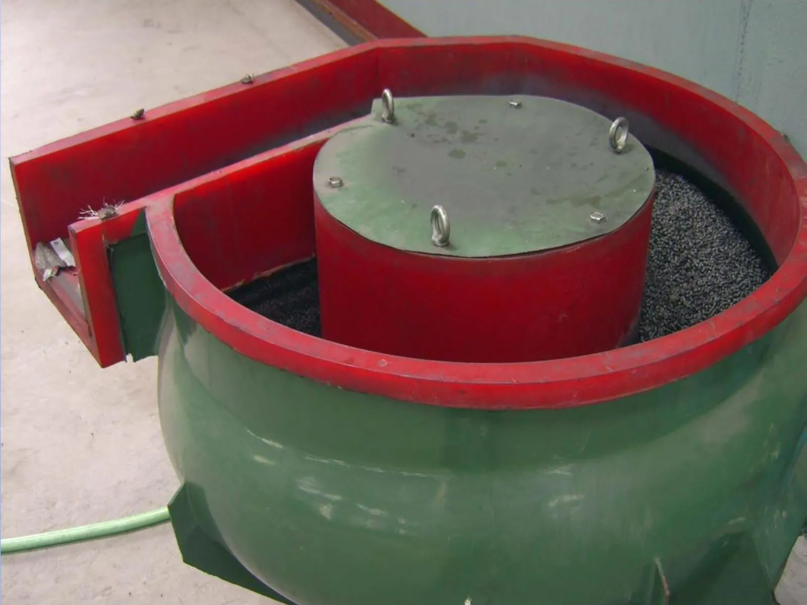
Mix the powder
Metal powder and small process additives are blended so every press stroke starts with the same feed.
See how powder becomes a finished PM part, which steps control size and strength, and where secondary operations are added.
Quick Answer
In simple terms, PM starts with metal powder, presses it into shape, heats it to bond the particles, and then adds finishing steps only where the drawing or function demands them. This page answers the process questions buyers and engineers usually ask before tooling is released.
Related Pages
Most sourcing teams do not need furnace chemistry first. They need a quick view of what happens, why it matters, and where cost or tolerance changes are introduced.
That is the goal of this section. Start with the simple flow, then move into the deeper process notes only if your part needs them.
Metal powder and small process additives are blended so every press stroke starts with the same feed.
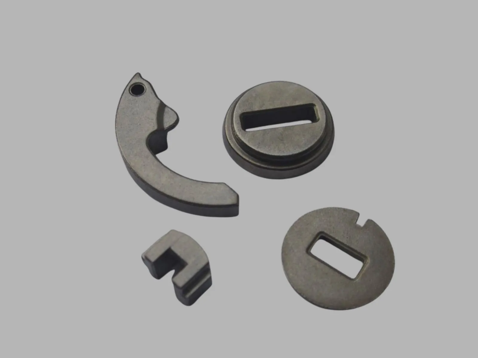
Tooling compacts the powder into a green part that already looks close to the final geometry.
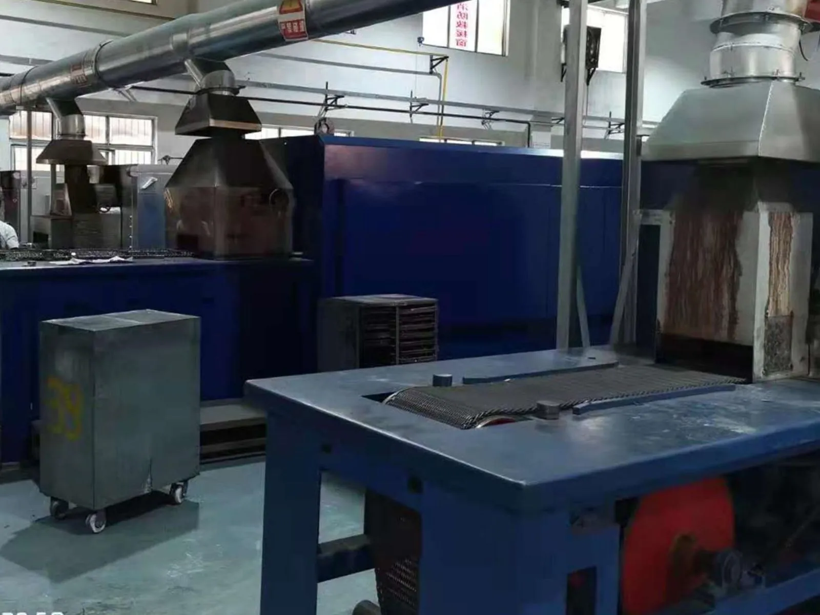
Heat bonds the particles and turns the green part into a usable metal component.
Sizing, machining, heat treatment, and inspection are added when function or tolerance requires them.
Because cost, tolerance, and lead time change at each step. A part that needs sizing, machining, and heat treatment will not behave like a simple as-sintered part.
They succeed when the shape fits compaction, annual demand is high enough for tooling, and secondary work is kept to the features that truly need it.
They get expensive when the design forces too many secondary operations or asks PM to do what another process does better.
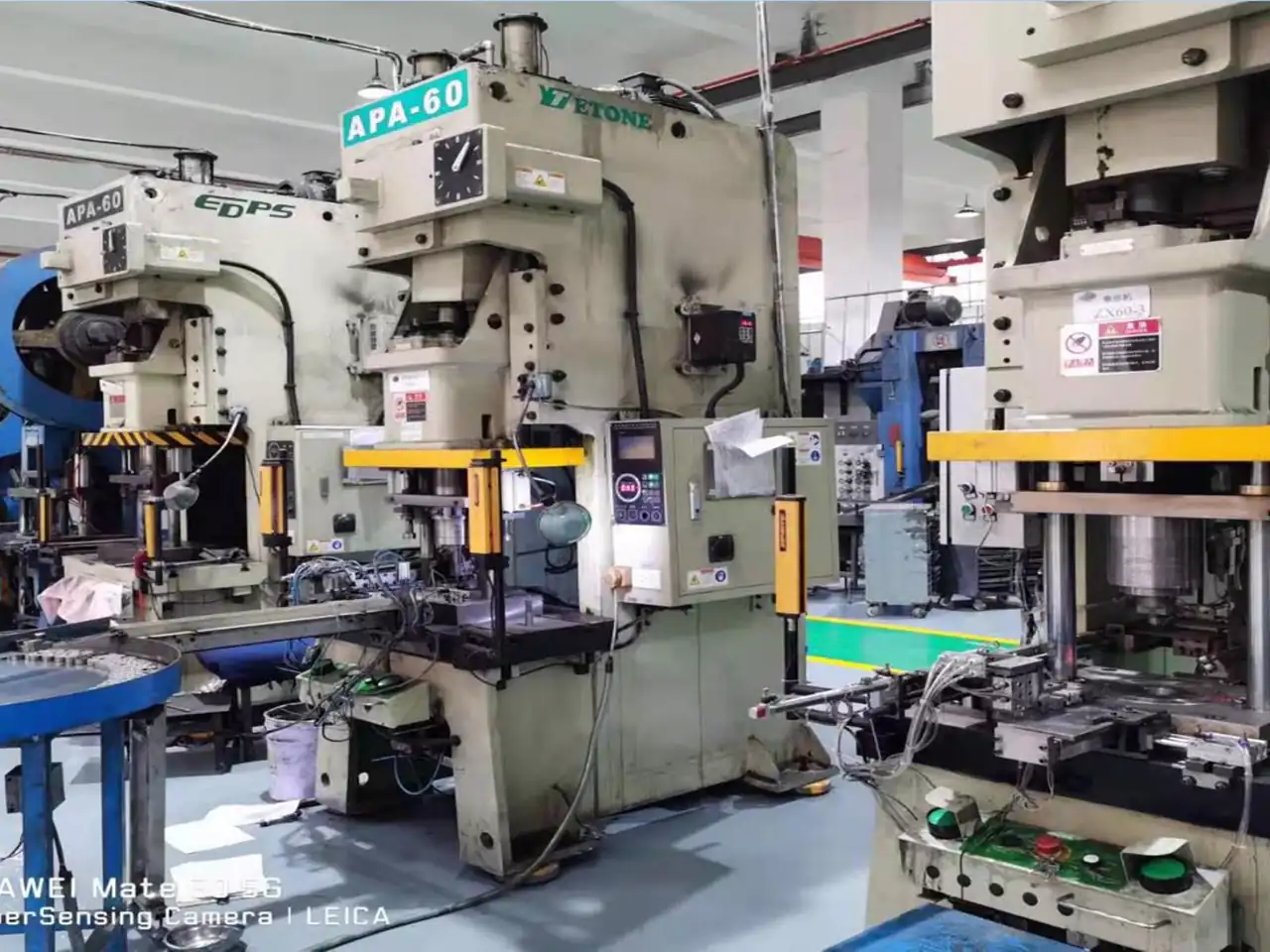
Powder Compaction
Compacting metal powder in precision tooling under high pressure to form green compacts with the target geometry and density.
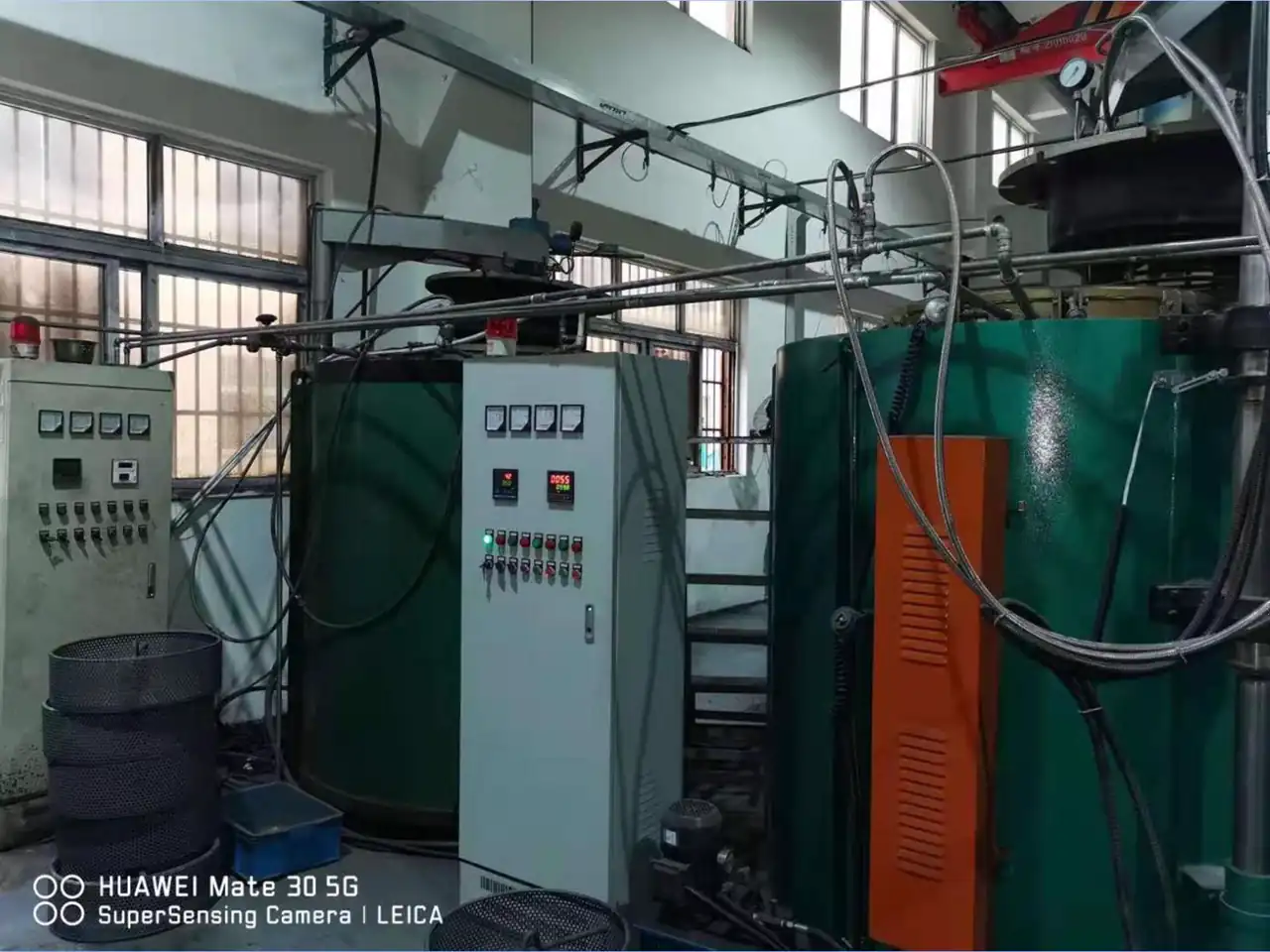
Controlled Atmosphere Sintering
Heating green compacts to high temperature in a protective atmosphere to form metallurgical bonds and deliver the required strength, density, and hardness.
Sizing & Coining
Re-pressing sintered parts in precision tooling to improve dimensional accuracy, density consistency, and surface finish.
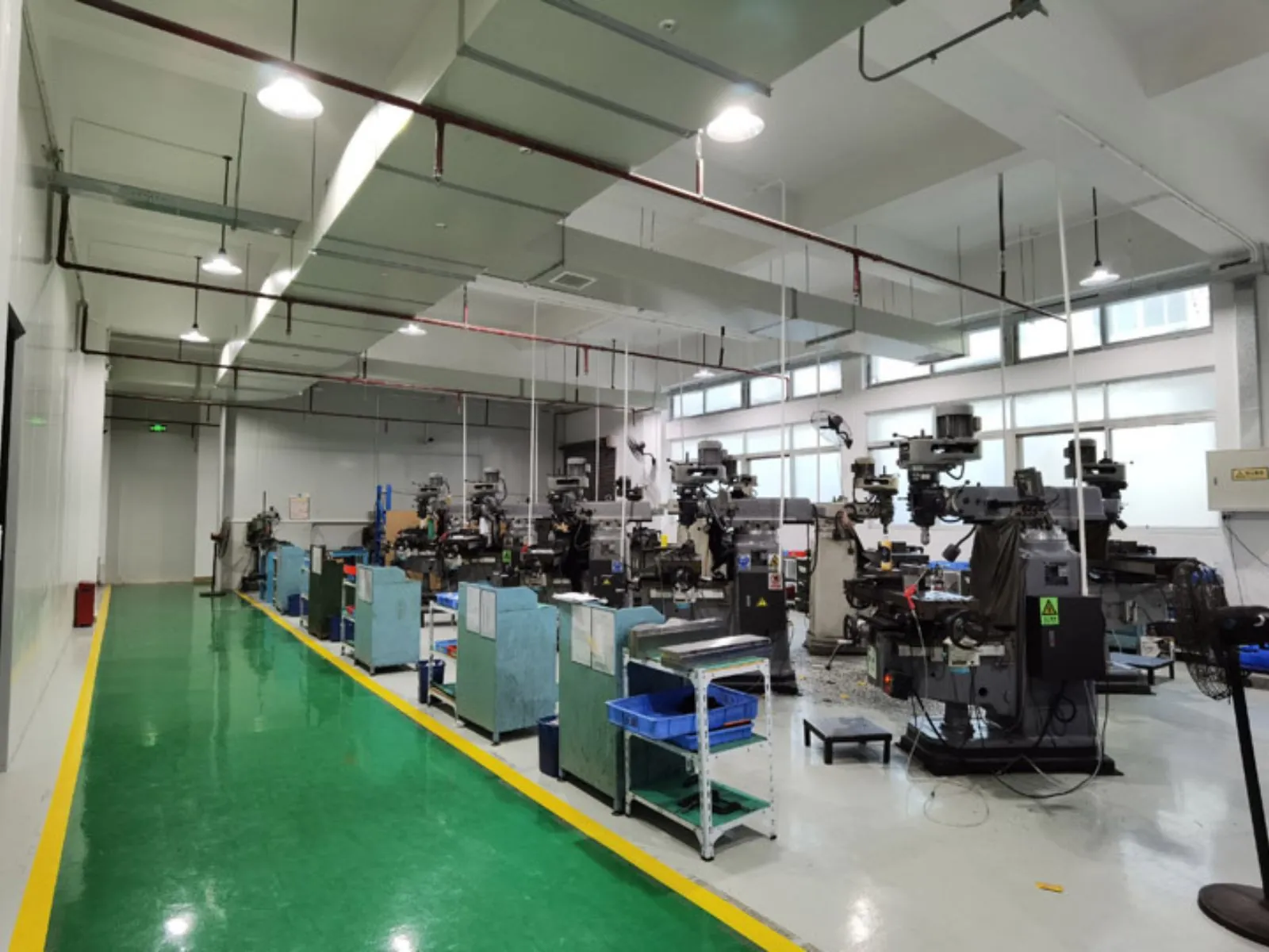
Secondary Machining
Precision CNC operations for critical holes, threads, faces, and other features that require tighter tolerances or special geometry.
Quenching, Tempering & Carburizing
Improving hardness, wear resistance, and strength through quenching, tempering, carburizing, and carbonitriding processes.
Steam, Oil, Plating & Coatings
Steam treatment, oil impregnation, electroplating, and protective coatings improve corrosion resistance, airtightness, and functional performance.
The inspection lab checks size, material condition, and durability so production stays close to the drawing and control plan.
| Equipment Name | Model | Accuracy / Spec | Purpose |
|---|---|---|---|
| CMM (Coordinate Measuring Machine) | Hexagon Global | +/-1 um | Dimensional accuracy inspection |
| Gear Measuring Center | Klingelnberg P-series | 0.5 um | Tooth profile and lead inspection |
| Element Analyzer | Spectro MAXx | 0.001% | Material composition analysis |
| Density Tester | Mettler Toledo | 0.001 g/cm3 | Density and porosity testing |
| Ultrasonic Flaw Detector | Olympus | 0.5 mm sensitivity | Internal defect detection |
| Salt Spray Chamber | Q-FOG | ASTM B117 | Corrosion resistance testing |
Powder composition, particle size distribution, and apparent density checks before production starts.
Continuous verification of compaction density, key dimensions, and visible defects during production.
Dimensional, functional, and appearance inspection based on the defined control plan and sampling level.
Packaging, labeling, documentation, and traceability verification before shipment release.
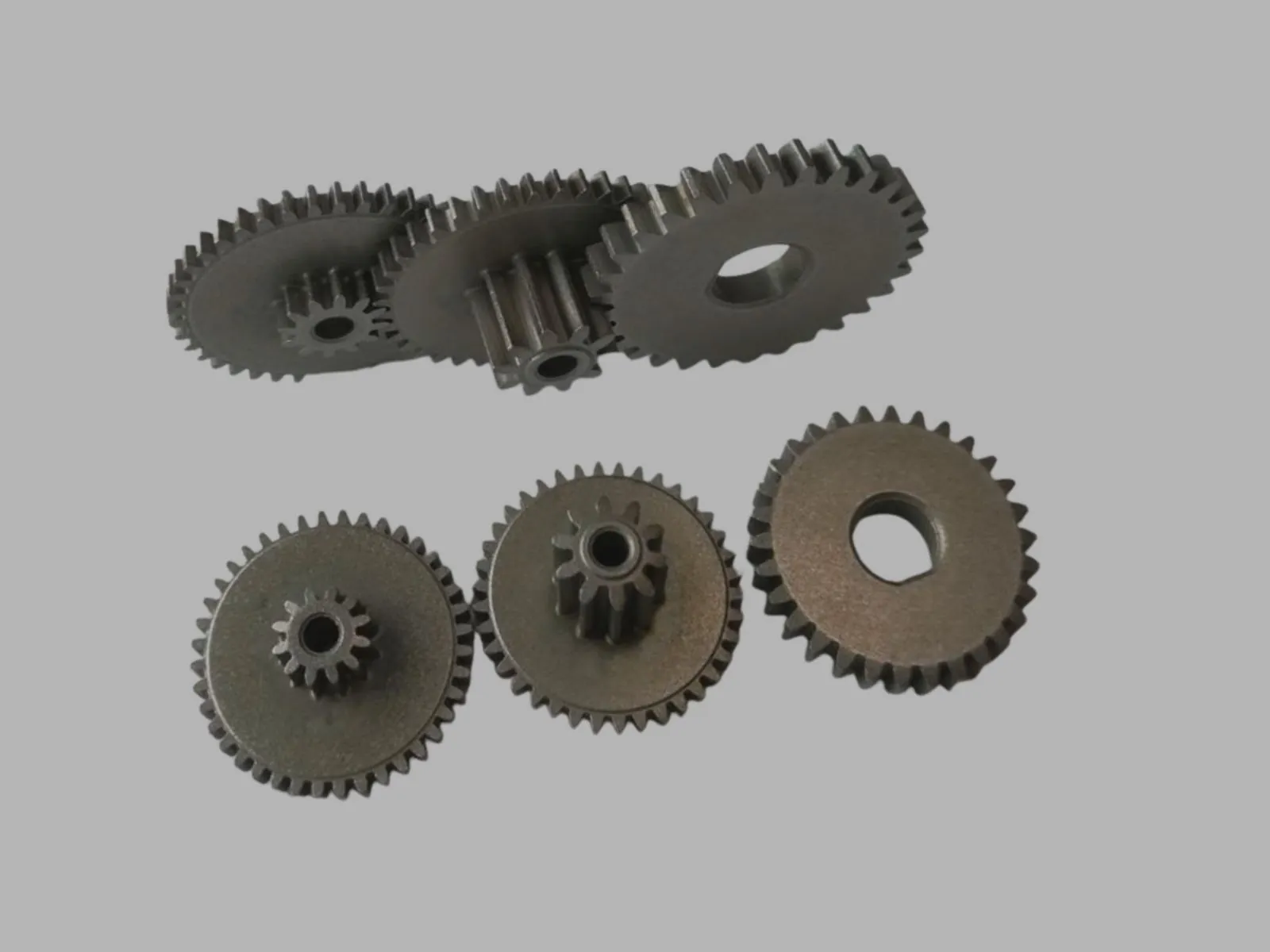
We use KISSsoft and dedicated measuring centers to manage shrinkage, tooth form, and inspection targets when a gear program needs tighter accuracy than a standard PM part.
Use these internal links to keep moving through the most relevant guides, service pages, and technical references for this topic.
See how GB9 gear work, KISSsoft design support, and process control fit into real PM gear programs.
Review when drilling, tapping, grinding, or CNC finishing is still required after sintering.
Compare steam treatment, oil impregnation, coatings, and corrosion-focused finishing options.
Learn how inspection plans, density checks, and traceability support stable export production.