Table of Contents
What VVT Stators and Rotors Do
A camshaft phaser is a hydraulic actuator mounted between the crankshaft timing drive and the camshaft. It uses pressurized engine oil to rotate the camshaft relative to its drive sprocket, advancing or retarding valve timing in real time under ECU control.
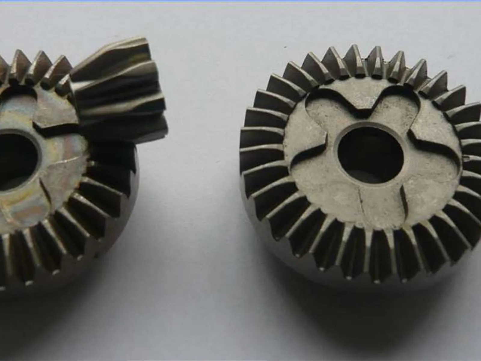
The stator is the outer body of the phaser. It has internal vane chambers that receive engine oil. The stator mounts to the timing chain sprocket and rotates at half crankshaft speed (on four-stroke engines).
The rotor is the inner body. It has radial vanes that fit into the stator chambers. Engine oil pressure on alternating sides of each vane rotates the rotor relative to the stator, creating the phase shift in camshaft timing. The rotor is fastened to the camshaft end.
Together, stator and rotor form the hydraulic cell that converts oil pressure into camshaft phase angle. The dimensional relationship between vanes and chambers determines:
- Phase angle range
- Oil leakage (which affects response speed and NVH)
- Mechanical durability
Why PM Is the Dominant Process for VVT Phasers
VVT stators and rotors have characteristics that make PM near-ideal:
High-volume, repeatable geometry. A typical engine program runs 100,000–500,000+ units per year. PM tooling produces millions of parts with consistent geometry and dimensional scatter measured in hundredths of a millimeter.
Complex radial vane profile in one pressing. The vane geometry—radial projections on the rotor, corresponding recesses in the stator—is a classic PM axial press geometry. The features form in the die during compaction, with no separate machining required to create the vane profile.
Oil passages and porting. Oil distribution features can be incorporated into the pressed geometry, eliminating or reducing drilling operations.
Material compatibility. Iron-based PM alloys provide the hardness, wear resistance, and dimensional stability needed for a component that operates in pressurized engine oil at elevated temperatures throughout the engine service life.
Tight OD-to-ID fit. After sizing, PM stators and rotors achieve the bore and OD tolerances required for the close vane-to-chamber clearance that minimizes oil bypass without creating binding.
Typical Materials
VVT stator and rotor components are typically produced from iron-based PM alloys. Common choices:
| Alloy Family | Typical Grades | Characteristics |
|---|---|---|
| Iron-copper | FC-0208, FC-0205 | Good strength, dimensional stability, lower cost |
| Iron-nickel | FN-0205, FN-0408 | Higher strength and toughness; better fatigue |
| Low-alloy steel (with heat treatment) | FLC-4608, FLN-4408 | Heat-treatable for high surface hardness |
| Diffusion-alloyed grades | Distaloy-based | Good mechanical properties; reduced shrinkage variability |
Final material selection depends on:
- Engine oil type and temperature
- Required hardness for wear resistance on vane tips and chamber walls
- Fatigue requirement from oil pressure cycling
- Program cost targets
Heat treatment (case hardening or through-hardening) is often applied to increase surface hardness on wear surfaces, particularly on rotor vane tips which experience repetitive contact with the stator.
All material specifications should be confirmed with the PM supplier based on the engine application requirements.
Key Dimensions and Tolerances
Dimensional control on VVT phasers is demanding by PM standards. Representative tolerance requirements for production parts:
| Feature | Typical Tolerance Range |
|---|---|
| Stator OD (mounting to sprocket) | ±0.025–0.050 mm |
| Stator ID (running clearance to rotor) | ±0.010–0.030 mm |
| Rotor OD (clearance to stator) | ±0.010–0.025 mm |
| Rotor bore (camshaft interface) | H6/H7 (±0.008–0.018 mm for typical diameters) |
| Vane width (rotor) | ±0.015–0.040 mm |
| Vane height (rotor-to-stator clearance) | ±0.010–0.025 mm |
| Part flatness (end faces) | 0.010–0.025 mm typical |
These tolerances are achieved through a combination of:
- Tight compaction tooling with precision punches and core rods
- Controlled sintering atmosphere and temperature profile
- Sizing (re-pressing) after sintering for bore, OD, and face flatness
- Selective grinding on tight-tolerance faces if required
Some programs require additional grinding or lapping of the end faces to achieve the flatness and surface finish needed to minimize oil leakage at the end plates.
All tolerance values are representative. Actual program requirements vary significantly and must be defined in the engineering drawing.
Production Volumes and Tooling
VVT phaser programs typically run at automotive volumes—100,000 to over 1,000,000 units per year across model life. This volume profile is ideal for PM:
- Hard tooling (carbide or tool steel punches and dies) amortizes over millions of parts
- Per-piece cost at high volume is significantly lower than machining from bar stock
- PM presses can run 10–30 cycles per minute for stator and rotor geometries, supporting high throughput
Tooling for a VVT stator or rotor typically requires a multi-level die set (upper punch, lower punch, core rods for internal features, floating die) and takes 8–16 weeks to design and manufacture at the start of a new program.
Tooling investment is program-specific and confidential, but automotive PM tooling of this complexity typically requires multi-year volume commitments to justify.
Design Considerations for PM VVT Parts
Vane count and geometry. Most VVT rotors use 3, 4, or 5 vanes. More vanes increase torque output and response speed but require tighter individual vane tolerances. PM can produce 3–5 vane geometries reliably; 6+ vanes are possible but require careful die design.
Oil passage placement. Oil passages should be oriented axially where possible to be formed in the die. Radial or angled passages require drilling, adding cost and potential for misalignment.
Wall thickness. Minimum wall thickness on stator vane chambers and rotor vane roots should be reviewed with the PM supplier early. Walls thinner than 2–2.5 mm can be problematic for compaction density and strength.
End face sealing. The end faces of the stator and rotor assembly bear against end plates. Low face flatness reduces oil bypass, which directly affects phase response time and NVH. If the PM flatness after sizing is insufficient for the program requirement, face grinding is the standard solution.
Lock pin features. Many VVT phasers include a lock pin assembly to hold the phaser at a default phase angle during cold start. If the lock pin bore or pocket is axially oriented, it can often be formed in the PM pressing. Radial lock pin features require secondary machining.
Quality and Inspection
Automotive VVT components require documented process control and first-article qualification. Standard PM automotive supplier expectations include:
- PPAP documentation (dimensional reports, material certifications, process FMEA)
- Cpk ≥ 1.33 on safety and function-critical dimensions
- Metallurgical reports (density, hardness, microstructure)
- Oil pressure cycle testing at the assembly level (typically conducted by the customer)
- ISO 9001 quality management system certification
SinterWorks PM holds ISO 9001 certification and has experience producing VVT and other automotive engine components for Tier 1 and Tier 2 programs.
Getting a Quote
For VVT stator and rotor inquiries, the most useful information to provide:
- 3D CAD file (STEP or IGES preferred) or 2D drawing
- Annual volume and program life (model year range)
- Target material or performance specification
- Key tolerance requirements (especially vane clearance and bore interfaces)
- Heat treatment requirement, if any
- PPAP level expected
Contact SinterWorks PM to discuss your VVT program requirements. We can review your design, advise on PM feasibility, and provide a formal quotation with process recommendations.
Frequently Asked Questions
Q: What are VVT stator and rotor components?
A: They are the stationary and rotating elements inside a variable valve timing (VVT) phaser that form oil chambers and vanes. Hydraulic pressure moves the rotor relative to the stator to advance or retard camshaft timing. Many programs use powder metallurgy for these parts at automotive volume.
Q: Why is powder metallurgy used for VVT parts?
A: PM produces near-net-shape vane and chamber geometry with good dimensional repeatability at high annual volume, reducing machining cost versus bar stock. Automotive programs from roughly 100,000 to over 1,000,000 units per year commonly justify PM tooling.
Q: What materials are used for PM VVT stators and rotors?
A: Programs typically use high-density iron-carbon or iron-copper PM grades with optional heat treatment for strength and wear. Material and density targets are defined in the OEM specification and validated through PPAP.
Q: What tolerances matter most on VVT PM parts?
A: Vane tip clearance, bore and hub interfaces, and end-face flatness directly affect oil leakage, response time, and NVH. Face grinding is often required when as-sintered flatness does not meet the assembly specification.
Q: What quality documentation is required for automotive VVT PM?
A: Expect ISO 9001, PPAP, dimensional Cpk on critical features, material certifications, and metallurgical reports. SinterWorks PM supports automotive PPAP and inspection reporting per program requirements.
Q: Can oil passages be formed in the PM die?
A: Axial oil passages aligned with the press direction are often formed in the die. Radial or angled passages usually require secondary drilling, which should be identified early in feasibility review.
Related Resources
Use these internal links to keep moving through the most relevant guides, service pages, and technical references for this topic.
Automotive PM Parts
See broader PM use cases across engine, transmission, and valve-train systems at automotive production volume.
Automotive Rocker Arms
Compare another valve-train PM application where fatigue, heat treatment, and repeat-volume economics all matter.
FN-0408 High Nickel-Copper PM
Review a higher-strength nickel-copper PM route that may fit demanding wear and fatigue conditions in automotive programs.
Request a Quote
Send your stator or rotor geometry, tolerance priorities, and annual demand for PM feasibility review and quotation support.