Design Guide
Powder Metallurgy Gear Design Guide: Key Points & Best Practices
From Tooth Profile Design to Die Manufacturing: The Complete Guide
Yao Qingpu
Powder Metallurgy Manufacturing Expert at SinterWorks Technology
Table of Contents
Quick Answer
PM gear design should account for sintering shrinkage, draft angle, density-related strength reduction, and the limits of pressed geometry. With good die design, realistic tooth parameters, and validation in tools such as KISSsoft, PM gears can support stable GB9-class production for many automotive and power tool applications.
Key Takeaways
- PM gears usually require shrinkage compensation in die design because dimensions change during sintering
- Draft angle must be balanced carefully so the part ejects reliably without sacrificing too much tooth-form accuracy
- Gear software such as KISSsoft helps validate tooth geometry, shrinkage allowances, and strength assumptions
- PM gear strength should be evaluated with density and porosity in mind rather than using dense wrought-steel values directly
- Sizing and limited post-machining can improve critical dimensions when the as-sintered gear alone is not enough
Introduction
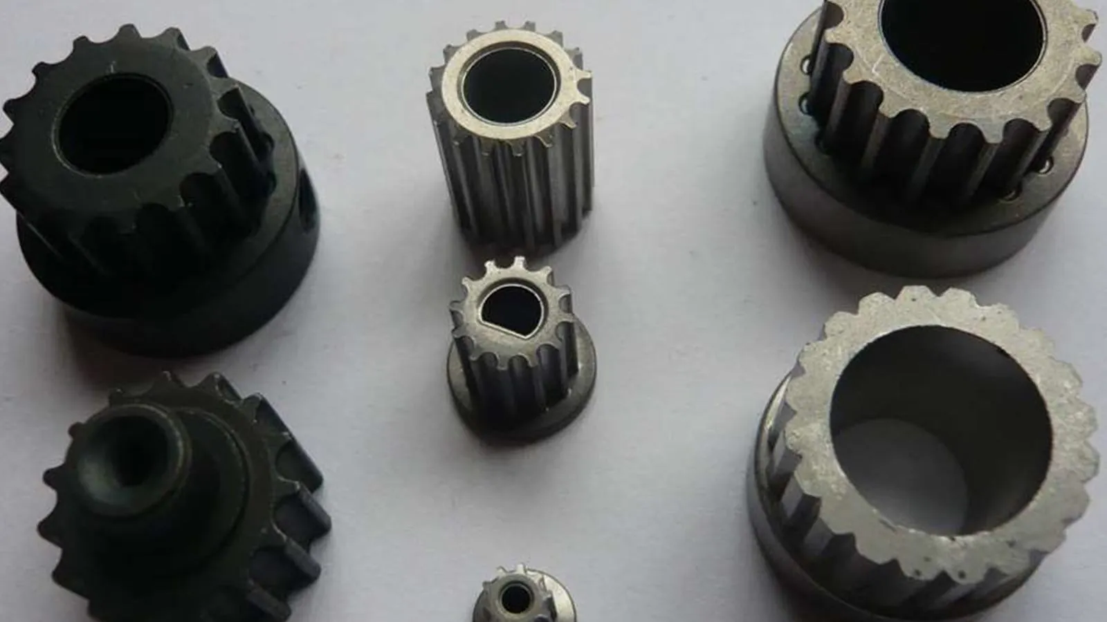
Powder metallurgy gears offer advantages such as low cost, high material utilization, and ability to form complex shapes in one operation. However, PM gear design differs significantly from machined gears, requiring special consideration of sintering shrinkage, density distribution, and other factors. If you want the production-side overview first, visit our powder metallurgy gears page.
PM Gear vs Machined Gear Differences
Manufacturing Method Differences
| Characteristic | PM Gear | Machined Gear |
|----------------|---------|---------------|
| Forming Method | Die pressing | Cutting/Machining |
| Material Utilization | >95% | 60-70% |
| Tooth Profile Precision | Affected by die and shrinkage | Directly determined by cutter |
| Surface Roughness | Ra 1.6-3.2 | Ra 0.4-1.6 |
| Internal Porosity | Yes (10-20%) | No |
| Strength | Slightly lower than forged steel | High |
PM Gear Design Process
Step 1: Determine Basic Parameters
Module
- Recommended range: 0.3-4.0 mm
- Small module: Low noise, relatively weaker strength
- Large module: High strength, more noise
- PM commonly used: 0.5-2.0 mm
Number of Teeth
- Minimum: avoid undercutting and confirm the minimum tooth count from your module, pressure angle, and profile shift
- Recommended range: 15-100 teeth
- PM advantage: Can directly form complex tooth profiles
Pressure Angle
- Standard: 20 degrees (general purpose)
- High torque: 25 degrees or 30 degrees
- PM recommendation: 20 degrees or 25 degrees
Step 2: Tooth Profile Design
Tooth Profile Compensation
Why compensation is needed:
During sintering, gears experience about 1-2% linear shrinkage, causing:
- Tooth thickness reduction
- Tooth tip sharpening
- Meshing clearance changes
Compensation Strategy: This work should be aligned with a practical DFM review before tooling release.
- Radial scaling: Die size = target size x (1 + shrinkage rate)
- Increased tooth thickness: Compensates for post-sintering thickness reduction
- Tooth tip circle adjustment: Prevents excessive sharpening after sintering
Shrinkage Rate Determination:
- Iron-based materials: 1.2-1.5% (radial)
- Copper steel materials: 1.0-1.3%
- Specific values determined through testing
Step 3: Die Design Considerations
Draft Angle
Axial Draft
- Tooth flank: 0.5-1.5 degrees
- Hub: 1-2 degrees
- End face: Can be designed flat
Impact
- Large angle: Easy ejection, reduced tooth profile precision
- Small angle: Difficult ejection, rapid die wear
- Balance: usually 0.5-1 degree
Using KISSsoft for Design
Software Advantages
KISSsoft is German professional gear design software supporting PM gear design, especially when paired with strong quality inspection and validation routines:
- Automatic shrinkage compensation calculation
- Tooth profile optimization suggestions
- Strength verification
- Die life prediction
Design Workflow
- Input Basic Parameters
- Module, number of teeth, pressure angle
- Material selection (PM material library)
- Operating conditions
- Generate Tooth Profile
- Select standard or optimized tooth profile
- Set shrinkage compensation coefficient
- Generate die tooth profile
- Strength Verification
- Bending strength
- Contact strength
- Consider porosity effects (PM factor 0.8-0.9)
PM Gear Strength Calculation
Material Strength Correction
PM materials typically have lower strength than dense materials due to porosity:
Correction Factors
- Density 6.6 g/cm3: 0.7-0.75
- Density 6.8 g/cm3: 0.75-0.8
- Density 7.0 g/cm3: 0.8-0.85
- Density >7.2 g/cm3: 0.85-0.9
Conclusion
PM gear design requires comprehensive consideration of materials, dies, and processes. Through proper design and process control, PM gears can achieve GB9-grade precision, meeting most application requirements.
Related Resources
Use these internal guides to keep exploring process planning, materials, quality control, and quoting steps for this topic.
GB9 Gear Precision: Premium Standard for Powder Metallurgy Gears
Understanding gear precision grade standards. Why is GB9 two grades higher than GB11? How do PM gears achieve automotive-grade precision requirements?
Tolerance Planning for Powder Metallurgy Parts: A Practical Guide for Engineers
Learn PM tolerance capabilities, IT grade standards, and how to plan for sizing or machining when tighter tolerances are needed. Practical guidance for design engineers specifying PM components.
Request A PM Quote
Send drawings and receive DFM feedback, process advice, and quotation support from the engineering team.
What Is Design for Manufacturability in Powder Metallurgy? DFM Rules & Checklist
Design for manufacturability (DFM) in powder metallurgy means designing a part around the constraints of die compaction and sintering — pressing direction, density flow, shrinkage, and tooling limits — before the die is built. These 8 rules prevent tooling problems, scrap, and delays.
Frequently Asked Questions
How should shrinkage be considered in PM gear design?
PM gears shrink during sintering, so die geometry must be compensated based on material behavior, density target, and validated trial data. Engineers usually account for radial shrinkage, tooth thickness change, and tooth tip geometry rather than applying a single blanket factor everywhere.
What does KISSsoft help with in PM gear design?
KISSsoft is commonly used to validate tooth geometry, contact behavior, and strength assumptions. In PM programs it is especially useful for reviewing compensated tooth form, verifying performance, and supporting tool and process decisions before release.
How should draft angle be designed for PM gears?
Draft angle should be just large enough to support reliable ejection and tool life without unnecessarily degrading tooth geometry. The correct value depends on part shape, die structure, and tooth area, so it should be reviewed together with the toolmaker and process engineer.
What precision level can PM gears achieve?
With sound tooling, stable process control, and suitable secondary operations, PM gears can support GB9-class precision for many mechanical and power tool applications. Higher local precision may still require sizing or selective machining.
How is PM gear strength calculation different from dense steel gears?
PM gears contain controlled porosity, so density and material data must be evaluated differently from fully dense wrought steel. Strength assumptions should reflect real PM density, heat treatment condition, and validated test data rather than dense-steel handbook values alone.
Expert Review
Yao Qingpu
Powder Metallurgy Manufacturing Expert at SinterWorks Technology
Yao Qingpu works with global buyers on powder metallurgy design review, material selection, tolerance planning, cost-down opportunities, and production feasibility. His experience covers PM gears, automotive components, structural parts, and practical DFM support for long-run manufacturing programs.